LED Replica Glasses - Progress Report
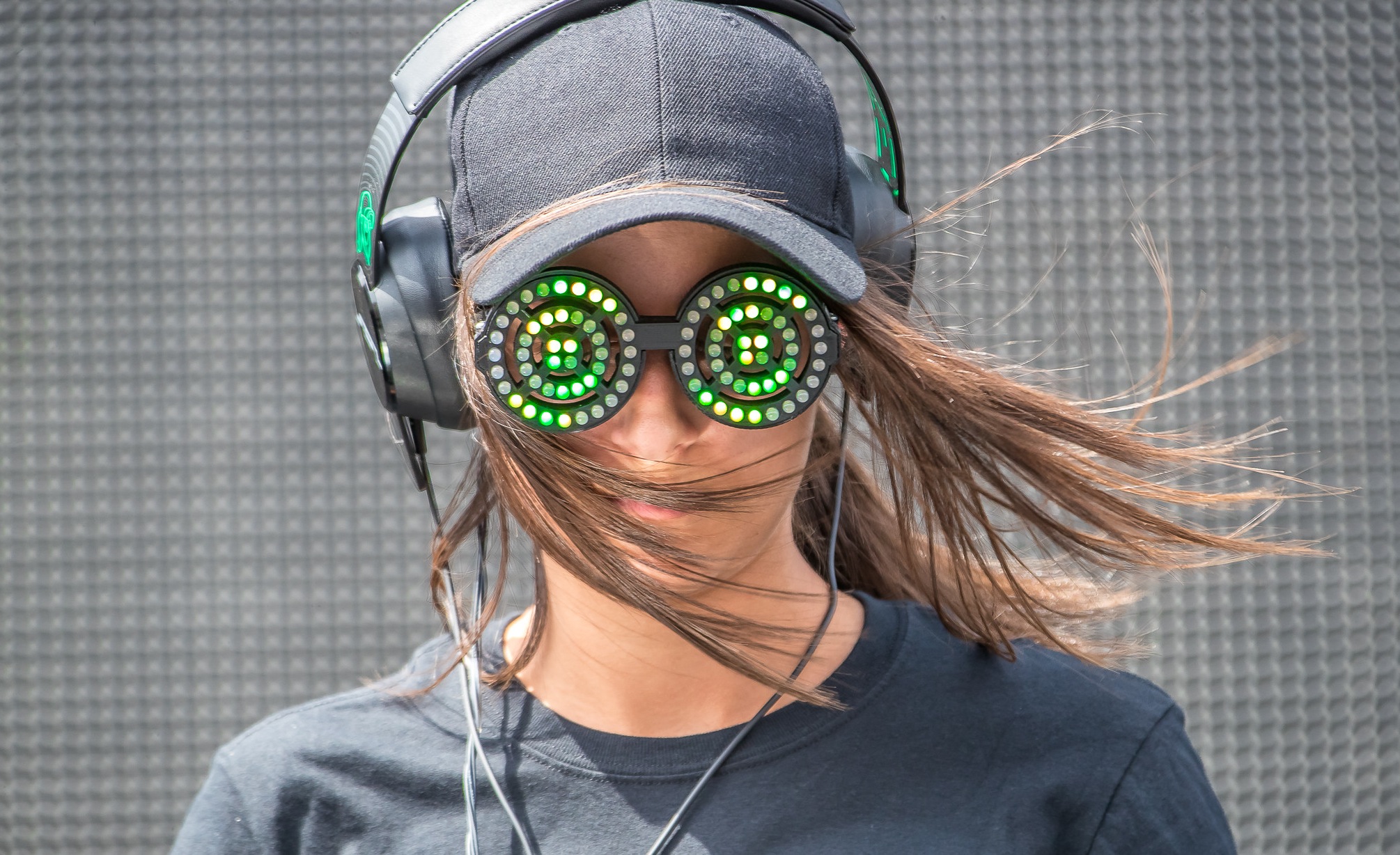
As a side project, I’ve been trying to recreate REZZ’s Crazy LED glasses. Seemed like a great and usable introduction to embedded programming, as well as using fields outside of programming (Electronics, 3D Design, possibly music).
There are other replicas currently made, most of them using various NeoPixel rings wired together. These are all impressive works, but they are a tad too different from the original glasses for my liking, I’d rather use through-hole pixels than the SMD versions.
A Teensy3 microcontroller is being used to power the glasses, due to its large memory, cost, and slim profile. Through-hole WS2812 LED’s (“NeoPixel”) were chosen due to being individually addressable, as well as being the right size.
Using custom Printed Circuit Boards seemed like the best way to go about this. With such a small space inside each frame, hand soldering LEDs together would be extremely cumbersome, and take up too much space as well. NeoPixels also advise the inclusion of a 0.1µF decoupling capacitor between each pixel, to prevent misbehavior. It’s unlikely a capacitor would also fit inside the frame.
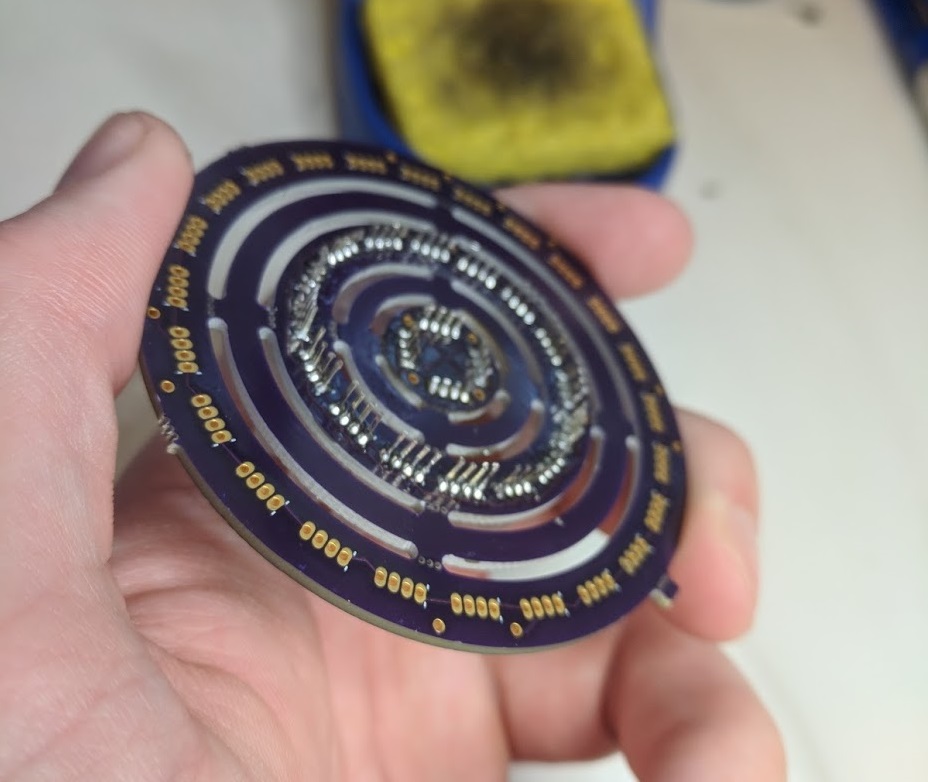
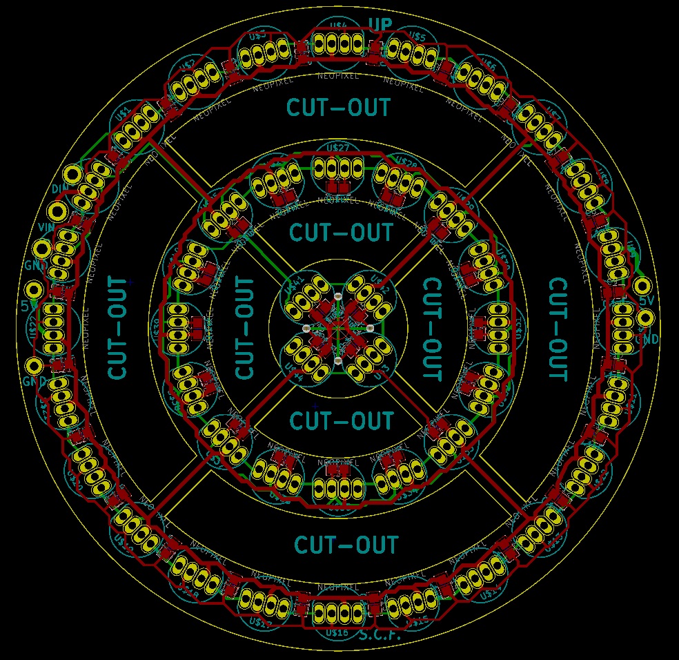
Circuit Layout and PCB design
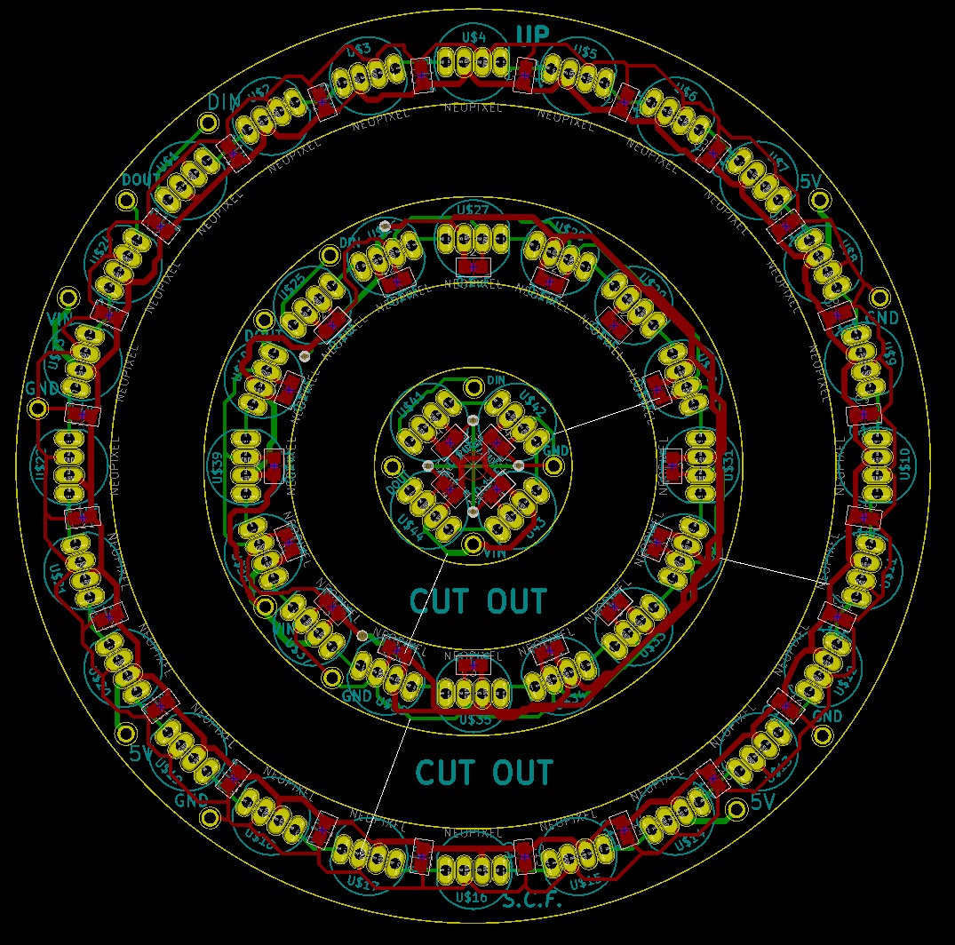
Each NeoPixel has a data_in, data_out, 5V, and GND pins. The first pixel starts at 9-0’clock
on the board’s outer ring, and continues clockwise until connecting to the next inner ring. There
are a total of 44 pixels; 24 on the outside, 16 in the middle, and 4 on the inside.
KiCAD was used to design the PCB, with the outline being imported from a AutoDesk Fusion 360 sketch. Getting the LED holes and Capacitor plates to the right radial position and angle was achieved by using KiCad’s Python scripting console (so nifty!). Being my first time ordering PCBs, I didn’t know if it was possible to connect the bridges between the rings, so I included pins on the internal rings for the data/power/ground to be hand wired.
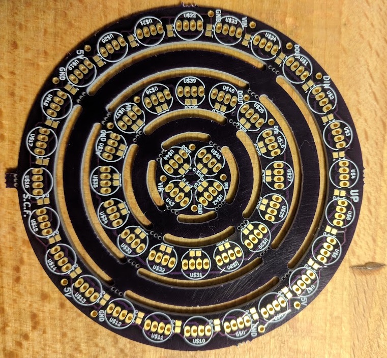
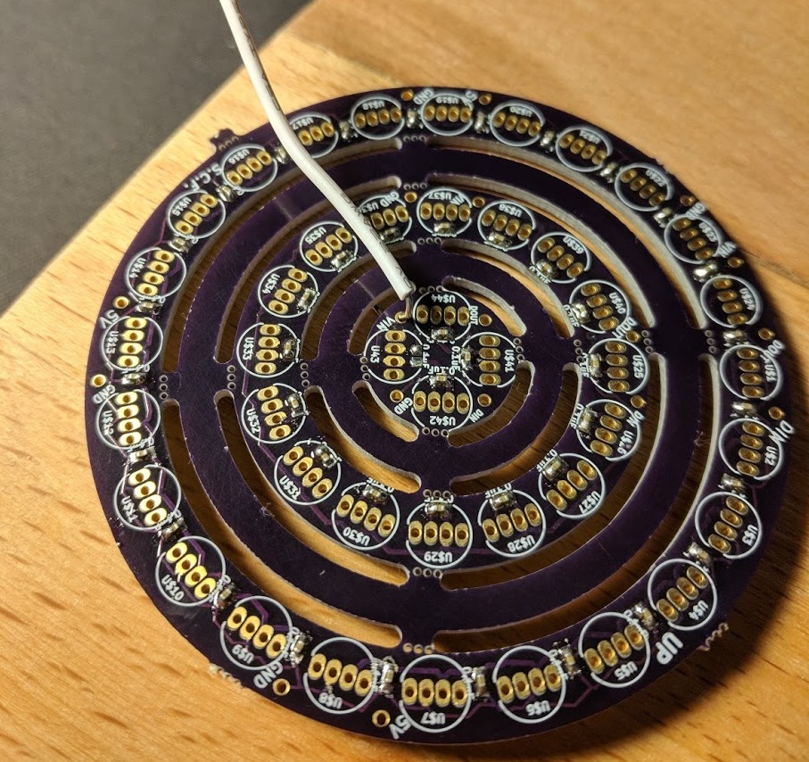
OSHPark was used to print the PCBs, turning out very well. (The purple color is lovely)
Each PCB was probed for faulty/crossing tracks, turning up nothing.
Soldering
I’ve never soldered before, so this was absolutely a learning experience
Firstly, SMD 0.1µF capacitors were soldered using a Reflow oven.
(This was a huge pain, I underestimated how small the capacitors would really be)
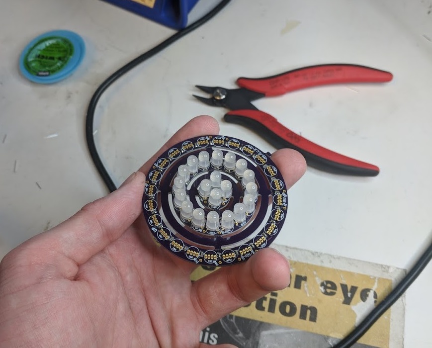
Soldering the LEDs was pretty straightforward, and eerily relaxing.
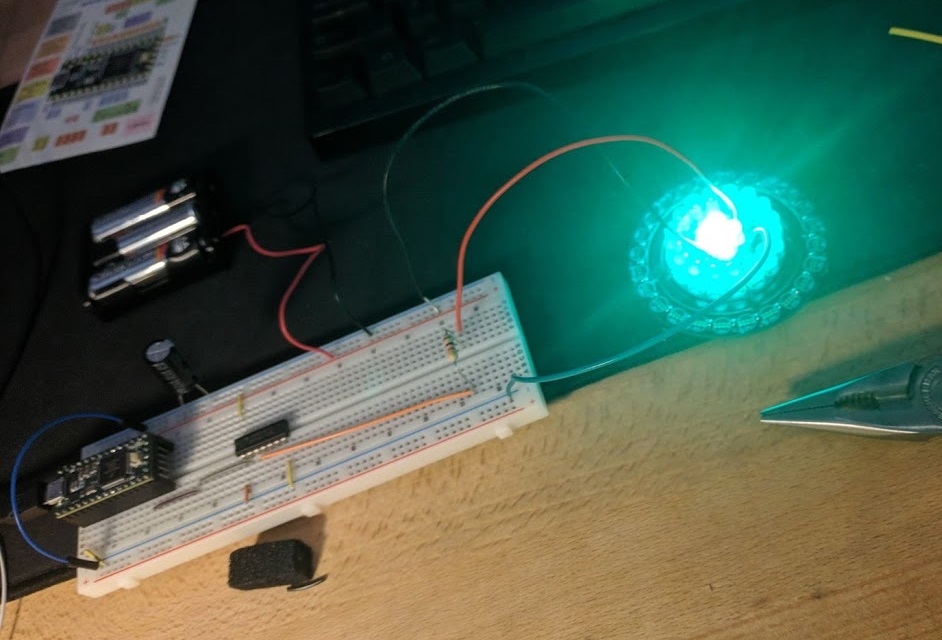
And some testing…
One fully soldered…
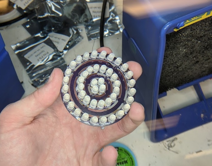
And now both soldered!
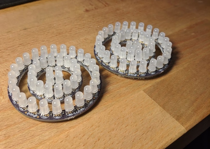
They turned out great!
I’d upload a demo video of them working later. But let me tell you, these things are bright. They’re so bright I can’t look at them without sunglasses on.
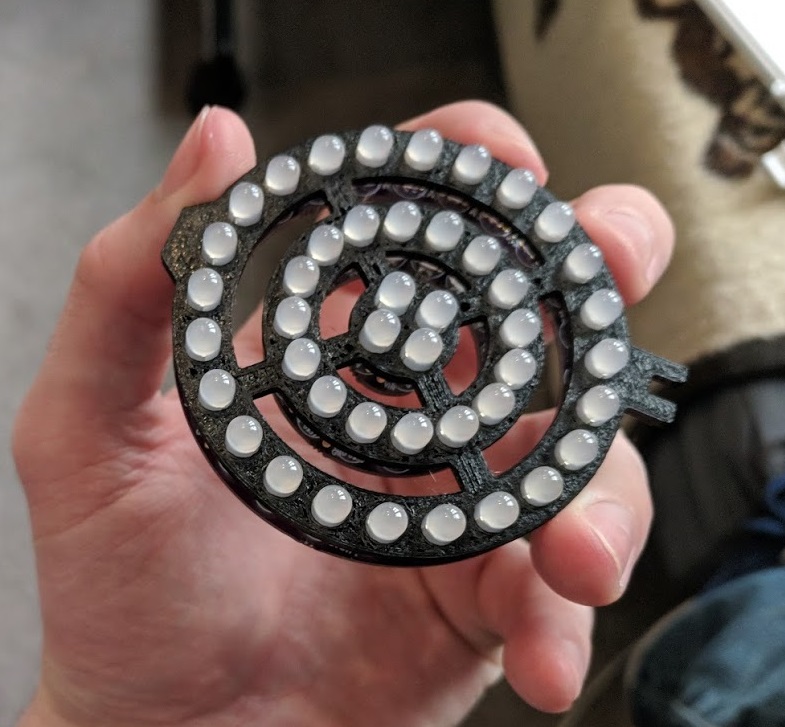
3d Printed Front Panel
I printed out a dummy front panel for just one side. The LEDs fit fairly snugly inside - no need for any screws holding it in
However, wiring turned out to be ugly. Big chunky wires between each ring – not so good if these PCBs are going to be in a compact space.
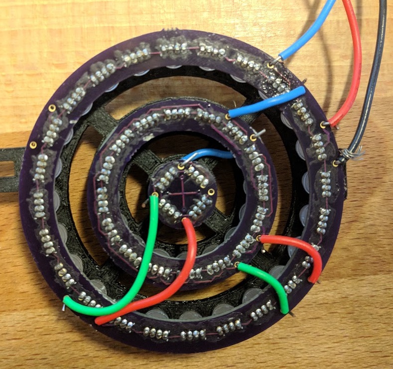
Yuck.
A good prototype, but we can do better.
Attempt #2
So some problem points with the first incarnation:
- Wiring between rings took too much space, looked bad, and were infuriatingly hard to attach wire to.
- Pin holes barely fit 22AWG wire.
- Pin hole lips are too small to solder wire and guarantee a good connection.
5V/GNDtracks do not need to come from one direction.5Vtracks should be wider for accommodation of bigger currents.
So, I redesigned and ordered another sets of PCBs to accommodate this.
Changes:
- Added Bridges between the rings, with tracks between for Data/Power/Ground.
- Increased width of
5Vtracks. 5VandGNDtracks branch at multiple spots to/from the inner rings, for better voltage distribution and flow.- Larger pin holes for 20AWG wires coming in, and 202WG wires between the two eyepieces.
- Wider pin hole lips for better soldering connection.
- Track Cleanup.
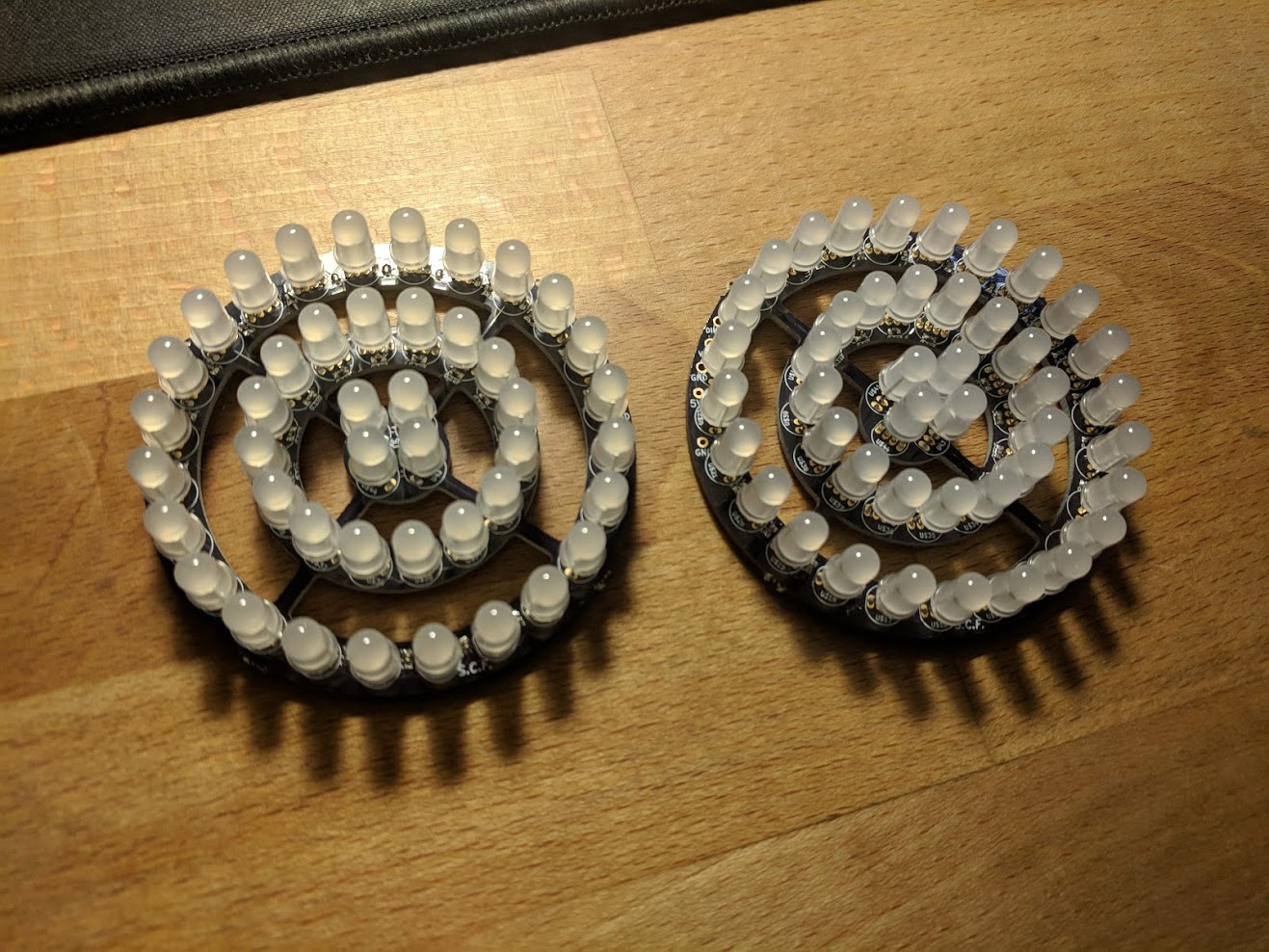
Schematics:
It was a decent surprise to see how well these PCB’s turned out with the bridges inserted. It took only 2 hours to solder the SMD capacitors on, and around 3 hours to solder the neopixels into place (including the time it took to desolder a faulty LED. Ugh).
That’s my current state of progress. Next comes the 3d printing, something I’ve been avoiding for a while. I’ll post another update when there’s decent progress.